Table of Contents
Selection guide — pairing the right coupling to a circuit. The five inputs below are the same checklist our engineers ask for on every RFQ, because a coupling is only as good as the fit.
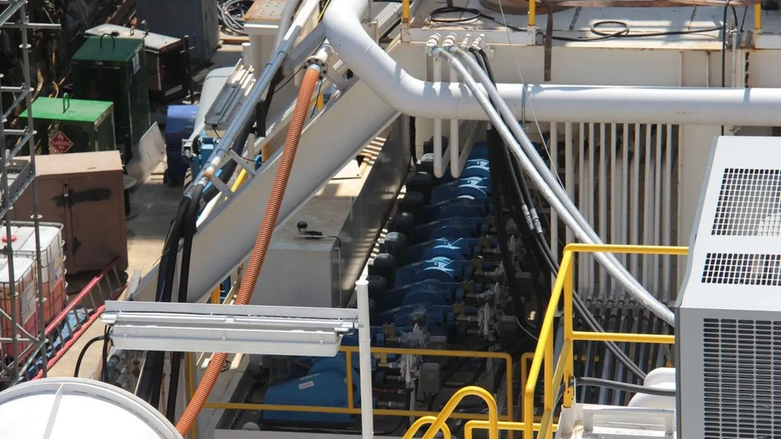
Why Coupling Size Matters More Than People Think
A hydraulic quick coupling is a flow restriction in the middle of a hose run. Oversize it and you pay more than you need to and add weight; undersize it and the coupling becomes the circuit’s bottleneck — pressure drop, heat, reduced actuator speed, and cavitation in extreme cases.
The good news: sizing a coupling is a five-input problem, and the first input (flow rate) does 80% of the work. This guide walks each input and ends with a sequence you can run in five minutes.
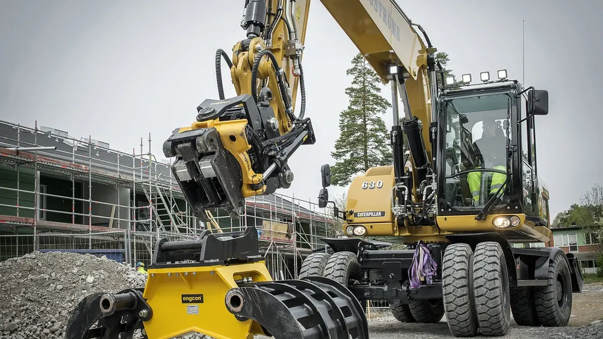
The Five Inputs
| # | Input | What it determines |
|---|---|---|
| 1 | Flow rate (L/min or GPM) | Coupling body size — the dominant input |
| 2 | System pressure + allowed pressure drop | Pressure rating and whether the size is adequate |
| 3 | Port thread + hose end | Thread size and standard (NPT/BSPP/JIC/ORFS) |
| 4 | Fluid compatibility | Seal material (see the O-ring guide) |
| 5 | Duty cycle + environment | Material (steel/brass/stainless), seals, locking style |
Input 1 — Flow Rate, the Master Input
Coupling size is expressed by the port/hose size (1/4”, 3/8”, 1/2”, 3/4”, 1”). Each size has a recommended flow range, and exceeding it is where the trouble starts.
| Coupling size | Typical continuous flow range | Typical recommended max flow |
|---|---|---|
| 1/4” | 8–20 L/min (2–5 GPM) | ~23 L/min (6 GPM) |
| 3/8” | 20–38 L/min (5–10 GPM) | ~45 L/min (12 GPM) |
| 1/2” | 38–76 L/min (10–20 GPM) | ~90 L/min (24 GPM) |
| 3/4” | 76–150 L/min (20–40 GPM) | ~170 L/min (45 GPM) |
| 1” | 150–300 L/min (40–80 GPM) | ~340 L/min (90 GPM) |
These are practical ranges for standard ISO 7241 couplings with steel bodies and standard poppet valves. Read the manufacturer’s flow-vs-pressure-drop curve for the exact model — that curve is the ground truth, and it differs between ball-lock and flat-face designs because the internal bore differs.
The rule of thumb: the coupling’s internal bore should be at least the same as the hose’s inner diameter. A coupling one size smaller than the hose is the most common sizing error in the field.
Input 2 — System Pressure and Pressure Drop
Every coupling has a rated working pressure (e.g. 250 bar / 3600 PSI for a 1/2” steel ISO 7241). Two numbers matter:
- Rated working pressure — must be ≥ your system’s relief setting, with margin. Flat-face couplings often carry higher ratings than ball-lock of the same size.
- Pressure drop at your flow — read from the flow curve. A good target is under 1.0 bar (14.5 PSI) drop at continuous flow for a line coupling. Above ~1.5 bar, consider one size up.
Pressure drop is roughly proportional to the square of flow, so a 40% flow increase quadruples the drop. That’s why “it worked for years” suddenly becomes “the cylinder is slow” after a pump upgrade.
| Symptom | Likely coupling problem |
|---|---|
| Actuator slow at full throttle | Undersized coupling → excessive pressure drop |
| Hose gets hot near the coupling | Flow through an undersized bore |
| Cylinder creeps under load | Internal leak past poppet (see the O-ring guide) |
| System pressure OK, flow low | Coupling bore smaller than hose bore |
Input 3 — Port Thread and Connection
The coupling body is useless without the right end connection. Two choices:
- Port thread — what the coupling threads into: NPT, BSPP, BSPT, JIC (SAE J514), ORFS (SAE J1453). Mixing standards is the single most expensive mistake in this category (see the thread standard guide).
- Connection style — male/female thread, or hose barb/female swivel for hose assembly.
Practical rule: for a quick coupling in a hose run, most buyers specify a female thread on the coupling (to accept a male hose end) or a male thread (to go into a port block). Match the thread standard of the rest of the circuit — don’t mix NPT and BSP on the same machine.
Input 4 — Fluid Compatibility
The seals must survive the fluid. The short version (full material table in the O-ring guide):
- Mineral hydraulic oil → NBR (nitrile) standard.
- High-temperature or aggressive → FKM (Viton).
- Phosphate ester / water-glycol → EPDM — never NBR.
A coupling’s seals are specified at purchase. If the machine runs a specialty fluid, say so on the RFQ — it changes the kit.
Input 5 — Duty Cycle and Environment
| Environment | Material choice | Why |
|---|---|---|
| Indoors, clean, dry | Steel (zinc-plated) | Best strength-to-cost |
| Outdoor, frequent washdown | Stainless steel | Corrosion resistance (see the material guide) |
| Marine / chemical washdown | Stainless or brass | Both resist corrosion; brass for lower pressure, non-spark preference |
| Mobile equipment, vibration | Steel with dust caps | Caps protect seals; see the maintenance guide |
Duty cycle note: a coupling that couples/decouples fifty times a day (skid steer) wears its seals and balls faster than one coupled once a week. The wear-rate difference is why the same size exists in multiple material/price tiers.
The Sizing Sequence
Run this in order — it takes five minutes with the machine’s spec sheet:
- Write down the flow rate (pump displacement × RPM, or the implement’s rated flow).
- Pick the candidate size from the flow table.
- Check the pressure rating against the system relief setting.
- Check the pressure drop at your flow on the model’s curve — target < 1.0 bar continuous.
- Match the port thread to the circuit standard.
- Confirm seal material against the fluid.
- Choose material by environment and duty cycle.
If any check fails, move one size up and re-check. The sequence is conservative by design: the cost of one size up is small; the cost of a bottleneck coupling is the whole machine’s performance.
FAQ
Q: Can I use a bigger coupling than the hose? A: Yes — a coupling one size larger than the hose is common and harmless; it just costs more and weighs more. The reverse (coupling smaller than hose) is the problem.
Q: Does a flat-face coupling have more pressure drop than ball-lock? A: At the same body size, flat-face (ISO 16028) couplings typically have a straighter bore and lower drop at moderate flows. But always read the specific model’s curve — bore geometry varies by manufacturer.
Q: How do I find my system’s flow rate? A: From the pump spec (displacement × RPM × volumetric efficiency), the implement’s rated flow in the machine’s manual, or a flow meter on the return line. The manual figure is usually the easiest and good enough for sizing.
Q: What if my flow falls between two sizes? A: Size up. The smaller size will be near its limit at continuous flow, and pressure drop rises with the square of flow — there’s no comfortable middle.
Q: Is brass strong enough for high-pressure lines? A: Brass couplings are typically rated for lower working pressures than steel of the same size. For circuits above ~150 bar, steel (or stainless) is the standard choice — the material guide has the detail.
NEXT STEP
Need the Right Hydraulic Quick Coupling for Your Machine?
Tell us the standard, size, thread and quantity — we respond within 24 hours with pricing and lead time.
Written by
Ray ChanHydraulic quick coupling sourcing specialist. Ray helps distributors, OEMs and maintenance teams find the right ISO 7241 / ISO 16028 / ISO 5675 couplings and replacement parts.